Introcdution
Automatic bollards are often specified with a short label such as K12, M50, PAS 68, or IWA 14-1. These labels look simple, but they describe a much more specific engineering result than many product pages suggest. A crash rating is not a universal strength score, and it is not a promise that any bollard will stop every vehicle in every location. It is evidence that a particular barrier configuration was tested against a defined vehicle, at a defined speed and impact angle, with the resulting penetration measured according to a recognized procedure.
For anyone selecting, specifying, or reviewing an automatic bollard system, that distinction matters. The visible steel cylinder is only one part of the protective system. The foundation, Poller spacing, control logic, road layout, drainage, soil, and maintenance condition all influence whether the installed system can deliver performance close to the tested result.
This article explains how crash ratings work, how the main standards differ, why older K ratings still appear in the market, and what should be checked before a rating is treated as meaningful.
What a crash rating actually describes
A vehicle impact is governed mainly by mass, speed, and direction. Kinetic energy increases with the square of speed, which means a vehicle travelling twice as fast carries approximately four times as much kinetic energy, assuming its mass is unchanged. A heavier vehicle also brings greater momentum and a different load path into the barrier. For this reason, “crash rated” is incomplete information unless the vehicle type, mass, speed, impact angle, and penetration result are also known.
In a full-scale test, the bollard or bollard array is installed in a defined test foundation. A remotely controlled vehicle is directed into the barrier. The test laboratory records the vehicle characteristics, approach speed, impact angle, barrier response, debris, and the distance that the vehicle or its cargo bed travels beyond the protected line. The result is therefore a performance classification for a tested system, not simply a material specification for a post.

The penetration result is particularly important. A barrier may stop a vehicle from crossing completely but still allow part of the vehicle to intrude into the protected area. A site beside a wide setback may accept more dynamic penetration than a narrow pedestrian entrance, a building lobby, or a queue immediately behind the barrier. The appropriate rating depends on the consequence of that intrusion, not only on whether the vehicle eventually stops.
ASTM International makes this limitation explicit. Its F2656/F2656M test method is designed to establish a penetration rating for vehicle perimeter barriers under vehicle impact, but it cautions that the result does not imply performance in all site conditions, approach routes, or topography. It also notes that a single-specimen test at a specified impact location does not validate every possible impact point. [1]
That is the first principle of interpreting a crash rating: read the complete test designation, not the largest number printed in a catalogue.
The main standards used for automatic bollards
ASTM F2656/F2656M
ASTM F2656/F2656M is widely used in North America and in projects that follow U.S.-based security specifications. It provides standardized impact conditions and penetration performance levels for both passive perimeter barriers and active entry-point barriers. The current ASTM page identifies the standard as a test method for crash testing vehicle security barriers and explains that agencies can select the vehicle conditions and performance levels appropriate to a defined threat. [1]
ASTM designations commonly combine a vehicle or impact condition designation with a penetration classification. In older and transitional documents, M30, M40, and M50 are often associated with a 15,000-pound medium-duty truck travelling at 30, 40, and 50 miles per hour respectively. The accompanying P rating describes dynamic penetration. Under the terminology summarized in U.S. Federal Highway Administration guidance, P1 means penetration of up to 1 metre, P2 covers more than 1 metre up to 7 metres, and P3 covers more than 7 metres up to 30 metres. [2]
Modern specifications should be read carefully because ASTM revisions and project documents may use different vehicle designations. A statement such as “M50 rated” is not a complete specification by itself. It should be accompanied by the applicable edition, vehicle description, penetration result, impact angle, test arrangement, and whether the result applies to a single bollard or an array.
PAS 68
PAS 68 was developed in the United Kingdom as a classification system for vehicle security barriers and their supporting foundations when subjected to a single horizontal impact. BSI’s description of PAS 68:2013 states that the specification covered both a vehicle impact method and a design method, including finite element analysis where it was validated by test data. It also made clear that the scope concerned vehicle impact rather than blast or ballistic resistance. [3]
PAS 68 designations are more detailed than a short K label. A typical result can identify the mass and category of the test vehicle, speed, impact angle, direction, and penetration or dispersion outcome. This makes the test record useful for comparing the tested threat with the actual approach conditions at a site.
There is an important current-status point. BSI lists PAS 68:2013 as withdrawn on 25 October 2023. That does not erase historical test results, but it means a new project should confirm which current standard or client specification is required rather than assuming that a legacy PAS 68 label is automatically equivalent to a current certification. [3]
IWA 14-1 and ISO 22343-1
IWA 14-1:2013 was created as an international framework for vehicle security barrier impact performance. ISO describes it as specifying the essential impact performance requirement and a test method for rating a vehicle security barrier subjected to a single impact by a test vehicle that is not driven by a human being. ISO now lists IWA 14-1 as withdrawn and identifies ISO 22343-1:2023 as the newer version. [4]
The related application document, IWA 14-2, addressed the selection, installation, and use of vehicle security barriers and the development of operational requirements. ISO likewise identifies ISO 22343-2:2023 as its replacement. [5] This transition illustrates a broader point: standards are living documents. A technical comparison should identify the edition and status of the referenced standard, especially when a project specification was written several years earlier.
PAS 68, IWA 14-1, and ASTM F2656 all use real vehicle impact testing, but their classifications and reporting formats are not interchangeable line by line. A product tested under one method may be suitable for a project using another method, but equivalence should be established by a qualified engineer or by the project authority. It should not be inferred from a similar-looking speed or weight value.
Where K ratings fit in
K ratings such as K4, K8, and K12 remain common in automatic bollard literature. They originated in earlier U.S. Department of State vehicle barrier testing and were historically used to express levels associated with the kinetic energy of a 15,000-pound test truck at different speeds. K12 is commonly associated with the highest of those traditional speed categories, while K4 and K8 represent lower energy levels.
The problem is not that the historical labels are useless. The problem is that they are frequently presented without the information needed to interpret them. The FHWA primer explains that the Department of State standard used a 15,000-pound diesel truck and that ASTM F2656 incorporated the standard test truck as the “M” designator. It also notes that the ASTM system expanded to include other vehicle types, such as passenger cars, pickup trucks, and heavy goods vehicles. [2]
Therefore, K12 should not be read as “this bollard can stop any 15,000-pound vehicle at 50 mph under any circumstances.” It should be read as a reference to a defined test regime, subject to the exact certificate and installation configuration. When reviewing a K-rated product, ask for the original test report or certificate, the test vehicle, impact speed, penetration result, impact angle, number and spacing of bollards, foundation arrangement, and any special conditions.
In current technical writing, M and P designations or the detailed formats used by international standards usually communicate more information than a standalone K label. K terminology remains useful for market continuity, but it should be translated into the underlying test parameters before a design decision is made.

Automatic bollards are systems, not isolated posts
An automatic bollard has two jobs that can conflict if they are not engineered together. It must provide a reliable physical barrier when raised, and it must retract or deploy safely and consistently during daily operation. The crash-tested condition concerns the first job, but the second job determines whether the bollard is actually in the protective position when it matters.
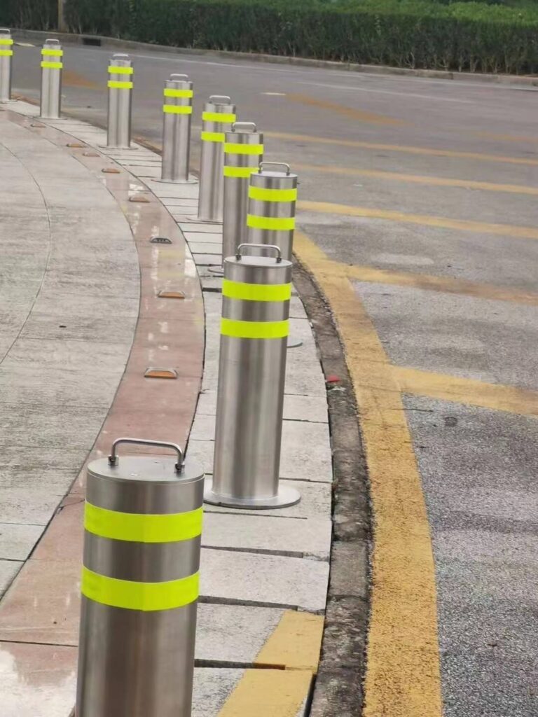
FHWA guidance describes active bollards as hollow steel pipes that retract into the ground or raise and lower to become flush with the road surface. It also states that the effectiveness of the system depends on how it disperses vehicle impact energy and that the foundation is critical, whether the design uses a deep or shallow foundation. Actuation may be pneumatic, electric, or hydraulic. [2]
This is why the phrase “crash-rated bollard” should not be separated from its installation details. A tested bollard installed in weaker soil, a smaller concrete foundation, a different reinforcement cage, or a different spacing arrangement is not necessarily the same tested barrier. The foundation transfers the impact load into the surrounding ground. If that load path changes, the performance can change even when the visible bollard is identical.
The array also matters. Some tests are performed with one bollard, while others use multiple bollards at a defined centre-to-centre spacing. The gap between posts, the connection between individual foundation units, and the width of the protected opening can affect the vehicle’s engagement with the barrier. A single-post test should not automatically be used to claim the same result for a wider entrance with several posts unless the test documentation supports that configuration.
How to read a test certificate
A useful test certificate should answer several practical questions.
First, what exactly was tested? The model number, bollard diameter, wall thickness, height above finished level, drive mechanism, number of posts, spacing, and foundation design should be identifiable. “A similar model” is not a reliable substitute for the tested configuration.
Second, what vehicle was used? Look for the vehicle class, gross vehicle mass, body type, axle arrangement, and any ballast. A passenger car, pickup, rigid truck, and articulated vehicle can interact with the same bollard in very different ways. The height and stiffness of the vehicle front also influence the load path.
Third, what were the speed and angle? A 90-degree impact is not the same as a glancing impact. Approach geometry, turning lanes, kerbs, and road gradients can alter the effective direction of impact. If the site permits a vehicle to accelerate over a long straight approach, a lower nominal operating speed at the gate may not describe the credible threat.
Fourth, what was the measured penetration? “Stopped” is not enough. The protected side may still experience vehicle intrusion, detached components, or debris. The acceptable distance should be set by the site layout and the assets or people behind the barrier.
Finally, what conditions were imposed after the test? Some active barriers may remain physically damaged but still be considered successful because they achieved the defined penetration limit. That can be an acceptable security outcome, but it is not the same as remaining operational after impact. A project may need two separate requirements: impact performance and post-impact availability or reset capability.
Site conditions that can change the result
A crash rating is most useful when the site reproduces the conditions assumed by the test. Soil is one of the most important variables. Dense, well-compacted ground can provide a different resistance and load distribution from loose fill, saturated soil, expansive clay, or a site affected by groundwater. Concrete strength, reinforcement, curing, drainage, and the connection between the foundation and pavement also matter.
Underground services can force a shallow foundation or a revised layout. That may be a practical solution, but it should be treated as a design change rather than an invisible installation detail. The FHWA guide notes that agencies should consider underground utilities and high water tables when selecting a foundation type for an active vehicle barrier. [2]
Drainage is also more than a maintenance concern. A retractable bollard pit that repeatedly floods can corrode components, damage sensors, interfere with limit switches, and reduce availability. Water management, heating where required, access for service, and protection of hydraulic or electrical equipment should be considered at the same time as the crash rating.
The approach route deserves equal attention. A barrier placed after a sharp bend may face a different impact condition from one at the end of a straight driveway. Kerbs and lane edges can lift or redirect a vehicle. A vehicle may also strike the barrier off-centre. ASTM itself warns that not all points of impact are necessarily tested and validated by a single-specimen test. [1]
Choosing a rating without overspecifying
The highest available rating is not automatically the best answer. An unnecessarily heavy barrier can increase foundation size, operating cost, noise, visual impact, and repair complexity. It may also create a false sense of security if the surrounding fence, gate, roadway, or building frontage is weaker than the bollard line.
A better process starts with a threat and consequence assessment. Identify the credible vehicle types, likely approach speeds, impact directions, and the distance that can be tolerated beyond the barrier. Then select the standard and rating that express those requirements clearly. Consider whether the site needs protection against accidental vehicle overrun, deliberate hostile vehicle attack, or both. These scenarios may lead to different design priorities.
Operational requirements should be included from the beginning. How often will the bollards cycle? What happens during a power failure? Is there a manual lowering method? Can emergency vehicles pass without delaying response? Are pedestrians separated from moving vehicles? Can the control system confirm that every bollard is fully raised before access is released? A barrier that is technically strong but frequently left lowered because it is inconvenient is not providing continuous protection.
Maintenance should be treated as part of the rating’s practical life. Inspect the visible post for corrosion, deformation, and impact damage. Check warning lights, induction loops, photocells, limit switches, hydraulic seals, control cabinets, drainage, and emergency release functions. After any collision, the complete system should be inspected rather than returning it to service because the bollard still moves.
A practical specification approach
A clear specification can state the required standard and edition, vehicle type and mass, impact speed, impact angle, penetration limit, bollard arrangement, foundation requirement, and environmental conditions. It can also require submission of the full test report or an independently verifiable certificate, not only a marketing label.
The specification should distinguish between tested performance and design intent. If the project uses a different soil profile, foundation depth, road slab, or bollard spacing from the test, the designer should explain how equivalence will be demonstrated. In some cases, that may require a structural calculation, a validated simulation, or a project-specific test. A calculation alone should not be presented as a full-scale crash test unless the applicable standard allows and describes that design route.
It is also worth checking the relationship between the automatic Poller and adjacent elements. Gates, fences, walls, barriers, kerbs, and pedestrian access controls should not create a bypass route. The protected line should be continuous enough that a vehicle cannot simply steer around the tested element. At the same time, the system should preserve safe escape routes and emergency access.
Final perspective
Crash ratings are valuable because they replace vague claims with repeatable test conditions. They allow designers and authorities to compare barriers using vehicle mass, speed, impact angle, and penetration rather than relying on appearance or steel thickness. But the rating only becomes meaningful when the tested configuration, foundation, array, site, and operating procedure are kept in view.
The most responsible way to describe an automatic bollard is not “indestructible” or simply “K12 rated.” It is to state what was tested, under which standard and edition, against which vehicle, at what speed and angle, with what penetration result, and under which installation conditions. That level of precision may look less dramatic than a single headline number, but it is far more useful for designing a barrier that performs as expected when the site faces a real vehicle impact.